Heating the House with Solar
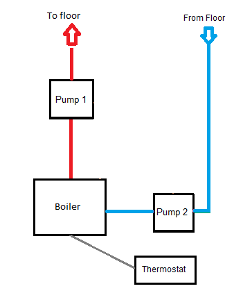
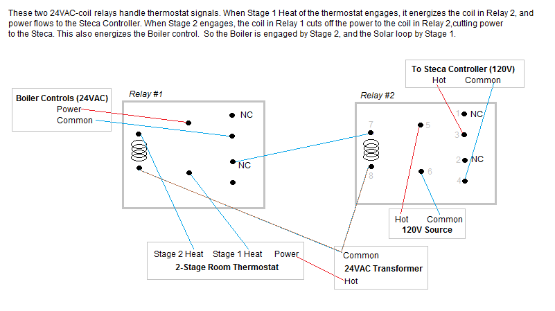
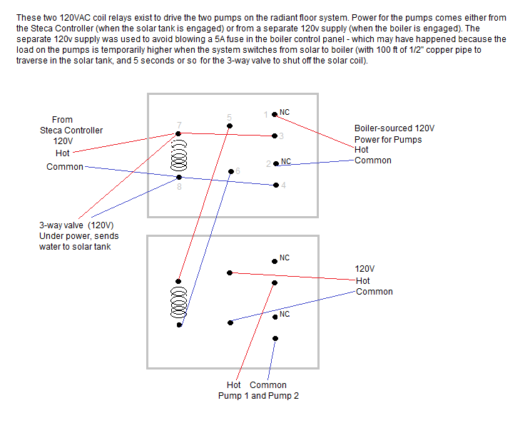
It was always my intention to use the system to provide some of our heat in the winter; this is why I made a 300 gallon tank and the 192 sq ft of collector (and of course the second heat exchanger coil in the tank). I knew we could not expect it to do the whole job, but I hoped for a significant solar contribution. The heating season has only just begun in earnest - so it is too early to tell how well the system will perform. I will report the results as they come in, but so far (Nov 22, 2010) they look promising. The radiant floor really sucks heat out of the solar tank. For example, during one night when the temperature was about 40 and windy, the tank went from 144 degrees to 104 by 7AM. In colder weather, of course, it will use even more of the tank's BTUs. What I face now is a decision about whether it makes financial sense to replace our inefficient LP water heater with an on-demand tankless LP unit or with an indirect-heated tank fed by the boiler. Otherwise, in winter, when I use the BTUs in the solar tank to help heat the house, I will be drawing on that inefficient water heater for DHW a lot. In summer, this is not an issue. If I install a tankless unit before the end of 2010 I can get a 30% tax credit. Our house is heated with an in-floor hydronic heat system. On the main floor and a loft, we have 1/2" pex tubing embedded in 1 1/2" of concrete that was poured on the plywood deck between 2x4s laid on the flat on 12" centers, with a hardwood floor over that. In the basement, we have pex in the insulated slab. The water is heated by a high-efficiency boiler running on LP. Two Grundfos pumps circulate the water. I wanted to make use of the existing pumps and plumbing when drawing heat from the solar tank. The idea is to simply not have the boiler firing when the solar heat is engaged. I am not pumping the tank water itself through the floor, but am harvesting heat from the tank by running the return water from the radiant floor through the 100 ft coil of 1/2" copper tubing. This all sounded simple in the abstract, before I really thought it through, but it required a bit of complexity to achieve the desired effect. Actually, for someone versed in electronics (particularly the use of relays), what I did would be child's play. It only seems complicated to those of us for whom relays and electronic 3-way valves seem esoteric. Now that I have been through the process, it seems pretty straightforward to me. Trying to describe this part of the system verbally is almost more of a challenge than building it (which is why engineers prefer diagrams). But I'll give it a shot. My boiler is "intelligent". It communicates with the room thermostat. It powers up the pumps when heat is called for. And it fires the boiler as needed based on some sophisticated algorithms. I wanted it to maintain all those functions, but only when the solar system was not able to keep the house warm by itself. The boiler ordinarily supplies 24v power to the thermostat, but since I wanted my new 2-stage thermostat to control not only the boiler but also the solar loop, I had to use an external 24vac transformer to power the thermostat (lest the "solar" stage turn on the boiler). A clever use of two 24vac relays achieved this. When thermostat Stage 1 calls for heat, it energizes the solar loop only. Stage 2 engages if the temperature drops further and/or a certain amount of time passes without achieving the target temperature in the house. When Stage 2 engages — after the solar has tried and failed to keep the house warm enough — the solar loop is shut down and the boiler takes over. I achieved this effect like this:- When Stage 1 calls for heat, it energizes a relay coil to send 120v current to a Steca differential controller (the exact same model that I use to drive the collection of heat from the solar panels). The Steca uses two sensors — one in the tank and one on the copper pipe that carries the water returning from the floor — to decide whether it is worth trying to draw heat from the solar tank. If it is, it sends 120v to a Bellimo 3-way valve, which opens so that the return water from the radiant floor gets diverted through the solar tank's heat exchanger. The Steca also sends power to the two pumps in the radiant system, to circulate the solar-heated water through the heat exchanger and through the floor.
- When Stage 2 calls for heat, it causes another relay to close, which cuts off power to the Steca controller, which closes the 3-way valve. This means that all circulating water will now skip the solar loop. The boiler also gets a heat signal at this point (in a closed loop with itself, thanks to the relay), and it then powers the pumps (the same pumps that are used when in solar mode), and fires as needed to generate heat.
 And here is the much more complex system now:
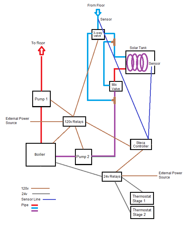 I hope this is pretty clear based on my verbal description. One thing to note is that I also used a thermal mixing valve at the tank. This exists so that in the rare case when the tank is very hot, I will not be sending too-hot water through the floor. We generally heat with water that is 105 degrees or so, and I did not want to send 150 degree water through. (I actually am not sure what the problems would be with this, but we have a hardwood floor atop the concrete, and I did not want to have repercussions there.) The mixing valve mixes in some of the cooler return water with the tank-heated water when the tank-heated water is too hot.
Now for the relays. I actually have four DPDT relays — two with 24vac coils, which handle the thermostat heat signals, and two with 120v coils, which distribute power to the pumps. I bought relays made by Omron Automation, from Allied Electric and Element14. They cost about $6 each. I also bought some sockets to make connecting wires to the relays infinitely easier — about $4 each. The relays are small cubes that look like this — alongside a socket:
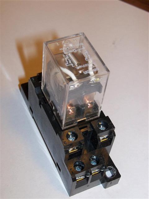
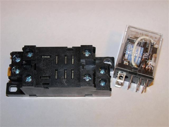 A relay inserted in a socket:
 Here is a diagram of the 24vac relays:
 And the 120v relays:
 My friend Tom Niedermeyer guided me through the process of learning about relays, and is the source of the elegance in these designs.
The 24vac relays I crammed into a junction box that is a little too constricted:
My friend Tom Niedermeyer guided me through the process of learning about relays, and is the source of the elegance in these designs.
The 24vac relays I crammed into a junction box that is a little too constricted:
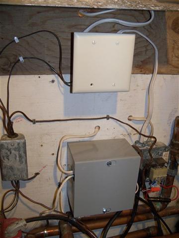
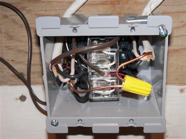 I used a larger box for the 120v relays:
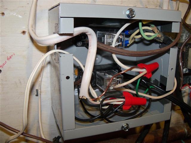 Here is what they look like with their covers on:
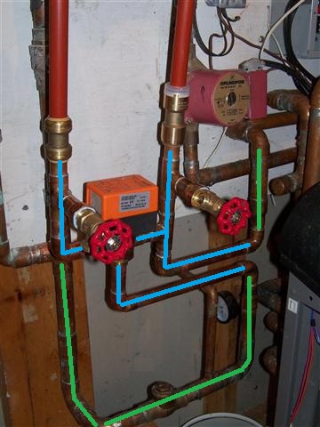
 The next picture is of the piping that connects to the solar loop. I cut into the 1" copper return pipe from the radiant floor (highlighted in green here for clarity) and brought two 3/4" pipes (in blue) to the 3-way Bellimo valve, which has an orange cap in the photo. When the valve is closed (normally) the water feeds right back to the 1" pipe. When open, the valve feeds the water through the solar heat exchanger loop, via 3/4" pex. I added the two hose bibs so that I could fill the heat exchanger tubing with water before starting up the solar loop for the first time — otherwise there would have been too much air to purge out of the system (thanks to my neighbor Rick Bellmer for this idea).
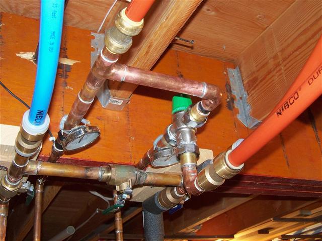
 Above the tank, the 3/4" pex eventually drops down to 1/2" copper. You can see the mixing valve here, with the green top:
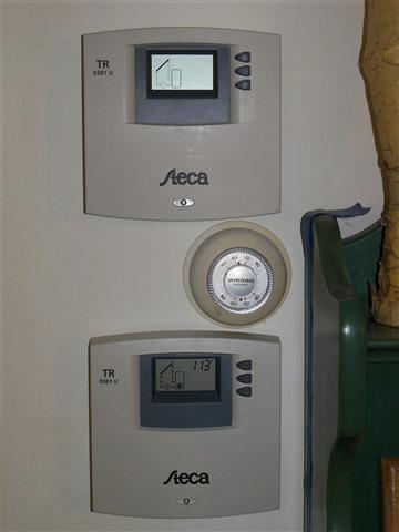
 Here are the two Steca controllers — one for the solar collector, one controlling the heat exchanger for the radiant heat system:
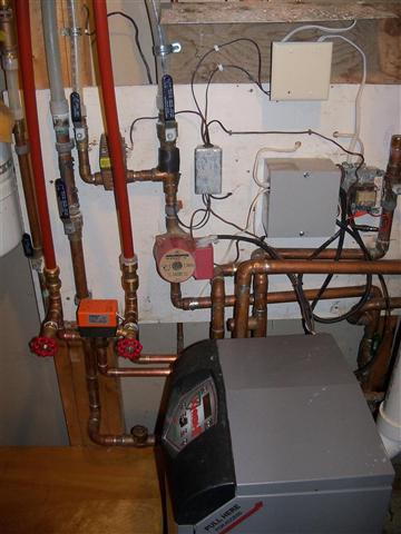
 Finally, here is a view of the boiler, the relay boxes, the 3-way valve and the start of the solar loop, and the rest of the radiant heat "core":
 Next page (Lessons Learned) >>